LIFT POSITIONING UNIT HP 2
| Delivery information | Fully assembled |
| ESD | Yes |
| Length in direction of transport [lT] | 1.60240320400481e+20 |
| Maximum load version [Fmax] | 1000N |
| Notice | Throttle check valve, exhaust air with push-in fitting, diameter ⌀ 6 mm, for thread G 3/8" must be attached by the customer,Permissible vertical process forces incl. WT 2,If the value is "0" at length in direction of transport [lT], HP 2 will be delivered with a lifting plate 3842516048 instead of the lift position plate for custom designing of the lift positioning plate |
| Permissible vertical process force | 1100N |
| Pneumatic straight connection [Ø] | 6mm |
| Preferred values | 160240320400480 |
| Recommended accessories | HP 2 Housing Element |
| Repetition accuracy | ±0,05 |
| Required accessories | Stop gate VE 2/...,Throttle non-return valve, exhaust air, G3/8", diameter Ø 6 mm,Sensor |
| Scope of delivery | Incl. fastening material,Switch bracket for mounting of M12 sensors top and bottom for lift position inquiry |
| Weight | 0kg |
| Workpiece pallet weight [mG] | 110kg |
| required compressed air connection [pmax] | 6bar |
| required compressed air connection [pmin] | 4bar |
- Positioning of a workpiece pallet in a processing station with high repetition accuracy requirements and higher workpiece pallet weights.
- Positioning using the positioning pins of the HP 2 and positioning bushings of the WT 2 workpiece pallet
- Lifting cylinder with adjustable damping of the upper and lower end positions
- Upper end damping takes effect only under full lift
- Infinitely adjustable lift height in 8 lift ranges hN from 0 ... 404 mm
- Can be combined with WT 2, WT 2/E, WT 2/F and WT 2/LS (only with version LS)
- Installation location AO = UB: Installation location under the conveyor section
- Installation location AO = AT: Installation location on the machine plate
- Installation location AO = O: Installation location for self-construction
- 1 - Positioning of a workpiece pallet in a processing station with high repetition accuracy requirements and higher workpiece pallet weights.
- 2 - Positioning using the positioning pins of the HP 2 and positioning bushings of the WT 2 workpiece pallet
- 3 - Lifting cylinder with adjustable damping of the upper and lower end positions
- 4 - Upper end damping takes effect only under full lift
- 5 - Infinitely adjustable lift height in 8 lift ranges hN from 0 ... 404 mm
- 6 - Can be combined with WT 2, WT 2/E, WT 2/F and WT 2/LS (only with version LS)
- 7 - Installation location AO = UB: Installation location under the conveyor section
- 8 - Installation location AO = AT: Installation location on the machine plate
- 9 - Installation location AO = O: Installation location for self-construction
, , Positioning using the positioning pins of the HP 2 and positioning bushings of the WT 2 workpiece pallet, Lifting cylinder with adjustable damping of the upper and lower end positions, Upper end damping takes effect only under full lift, Infinitely ad


Required accessories
| Stop gate VE 2/... |
| Throttle non-return valve, exhaust air, G3/8", diameter Ø 6 mm |

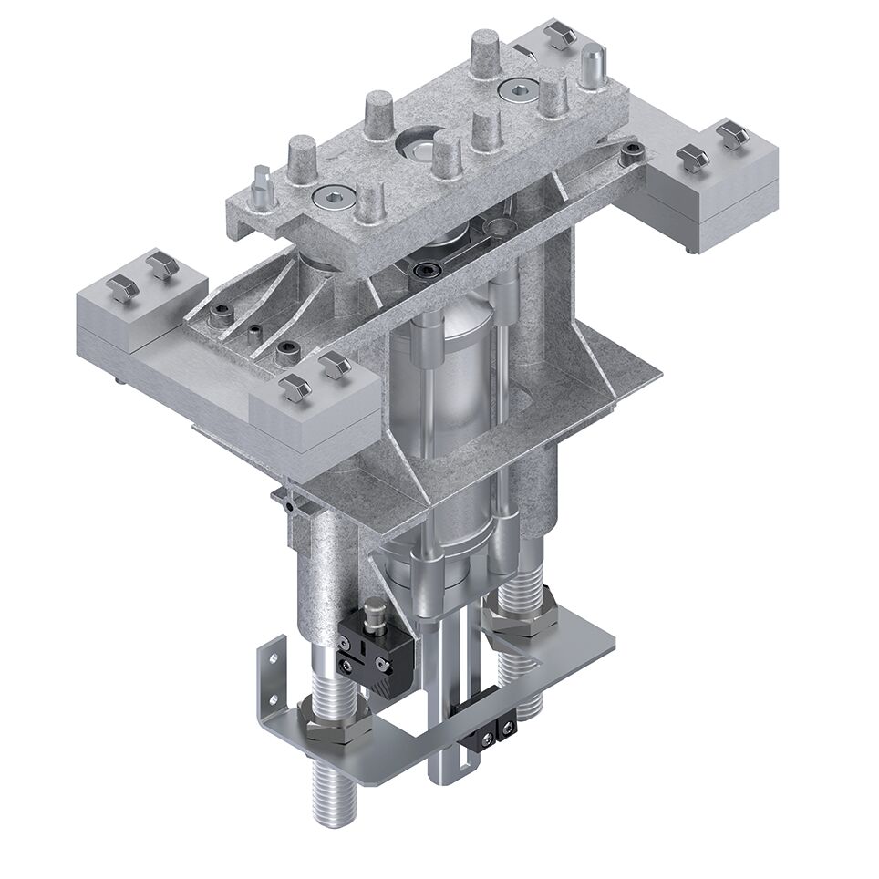
Lift Positioning Unit HP 2

| 1) | Lifting plate |
Lift Positioning Unit HP 2

Lift Positioning Unit HP 2

* = eccentric position for workpiece pallet with LT = 160 mm
1 = fastening kit (UB or AT)
2 = positioning plate
h0 = WT lift above conveying level
hG = cylinder total lift
Damping at the upper end takes effect only under full lift. For larger lifts, we recommend mounting the workpiece pallet separately while the HP 2 is in the top position in order to improve positioning accuracy.

| 1) | Not included in the scope of delivery |
|
No. |
3842999678 | ||
|
Max. total weight of workpiece pallet |
mG |
kg |
110 |
|
ESD |
yes | ||
|
Required compressed air connection |
p |
bar |
4 ... 6 bar |
|
Pneumatic push-in fitting |
Ø |
mm |
6 |
Lift range
|
Cylinder total lift |
Nominal stroke |
WT lift above conveying level |
|
hG |
hN |
h0 |
|
(mm) |
(mm) |
(mm) |
|
80 |
55 |
0 ... 59 |
|
125 |
100 |
60 ... 104 |
|
175 |
150 |
105 ... 154 |
|
225 |
200 |
155 ... 204 |
|
275 |
250 |
205 ... 254 |
|
325 |
300 |
255 ... 304 |
|
375 |
350 |
305 ... 354 |
|
425 |
400 |
355 ... 404 |
Compressed air consumption of TS 2plus units
Request Quote
How to Find Us
If you have any questions, just fill in the contact form, and we will answer you shortly. If you are living nearby, come visit us.