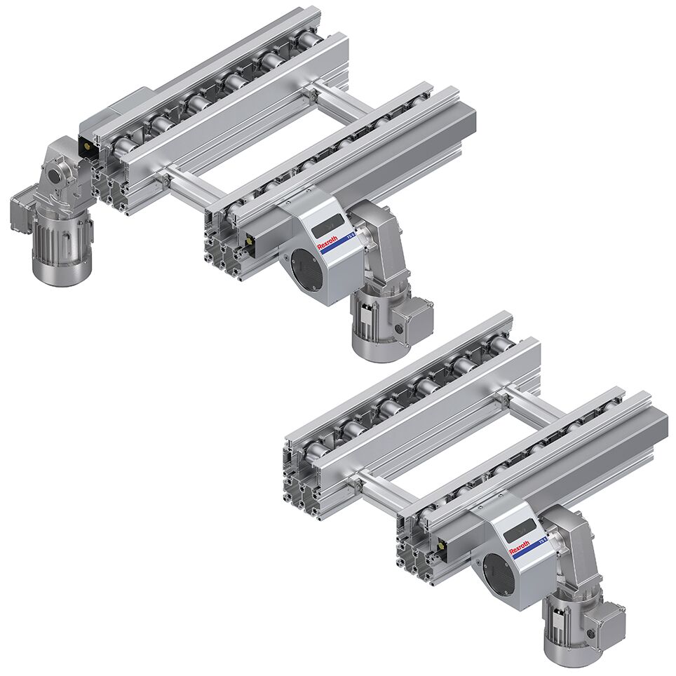
DRIVE MODULE AS 5/OC
| Delivery information | Ready-to-install, gear motor enclosed separately,Mounting option for the gear motor on the right/left possible |
| Gear motor [GM] | 0 = Schnittstelle SW27 ohne Getriebemotor,1 = Schnittstelle SW27 mit Getriebemotor,2 = Schnittstelle zu SEW Rundwelle Ø 20 ohne Getriebemotor |
| Lateral guide material [LG] | 1 = Stahl,2 = Kunststoff,3 = Aluminium |
| Length max [l max] | 390mm |
| Length min [L min] | 4160mm |
| Material information | Shaft: Brass |
| Motor connection [AT] | S = Kabel/Stecker,K = Klemmenkasten |
| Number of rollers [N] | 3; ... 12; 16; 21; 32 |
| Preferred values | 4556508451040 |
| Roller material [TR] | 1 = Stahl, verzinkt,2 = Stahl, nitrocarburiert |
| Weight | 0kg |
| Workpiece pallet length [lWT] | 4556508451040 |
- Drive for ST 5/OC… conveyor units
- Reversible operation possible
- Accumulation operation possible
- Motor connection with plug (AT = S) or terminal box (AT = K)
- Freely selectable motor position and length
- Gear motor can be mounted on both sides on the transmission drive (MA = R and MA = L)
- Viewing window for checking the toothed belt
- Due to the simple and space-saving disassembly of the cover, adjacent components/machines can be positioned at a distance of 20 mm from the AS 5
- Optional frequency converter
- Suitable for clean room of ISO class 7
- Suitable for dry room
1% RH - Notice: Please take account of the load center of gravity when selecting the drive
- 1 - Drive for ST 5/OC… conveyor units
- 2 - Reversible operation possible
- 3 - Accumulation operation possible
- 4 - Motor connection with plug (AT = S) or terminal box (AT = K)
- 5 - Freely selectable motor position and length
- 6 - Gear motor can be mounted on both sides on the transmission drive (MA = R and MA = L)
- 7 - Viewing window for checking the toothed belt
- 8 - Due to the simple and space-saving disassembly of the cover, adjacent components/machines can be positioned at a distance of 20 mm from the AS 5
- 9 - Optional frequency converter
- 10 - Suitable for clean room of ISO class 7
- 11 - Suitable for dry room
1% RH - 12 - Notice: Please take account of the load center of gravity when selecting the drive
Accumulation operation possible, Reversible operation possible, Motor connection with plug (AT = S) or terminal box (AT = K), Freely selectable motor position and length, Gear motor can be mounted on both sides on the transmission drive (MA = R and MA = L


Connection Kits

Connection Kits
Profile connector Intermediate plate CouplingCAD data
SZ 5/OC Leg Set

SZ 5/OC Leg Set
Leg sets for Open Center sectionsCAD data
Condition of Delivery
| Ready-to-install, gear motor enclosed separately |
| Mounting option for the gear motor on the right/left possible |
AS 5/OC drive module (Open Center), division p = 130 mm

AS 5/OC drive module (Open Center), division p = 195 mm; p = 260 mm; p = 325 mm

Division p and drive position DP
p = 130 mm
DP is the roller to which the transmission drive is fitted. This roller is not driven.
Example: DP = 2

Possible drive positions DP with division p
|
p (mm) |
MA |
DP |
|
130 |
R; L |
1 ... 31 |
Note:
Only if p = 130 mm: Roller corresponding to DP is not driven.
Gear motor can be mounted on both sides.
Permissible position lDP (mm) from start of section: lDP = DP x p - p/2
Example of p = 130 mm and DP = 10: lDP = 10 x 130 mm - 65 mm = 1235 mm
Division p and drive position DP
p = 195 mm; p = 260 mm; p = 325 mm
DP is the space between two rollers in which the transmission drive is fitted.
Example: DP = 1

Division p and drive position DP
|
p (mm) |
MA |
DP |
|
195 |
R; L |
1 ... 20 |
|
260 |
R; L |
1 ... 15 |
|
325 |
R; L |
1 ... 11 |
Permissible position lDP (mm) from start of section: lDP = DP x p
Example of p = 260 mm and DP = 5: lDP = 5 x 260 mm = 1300 mm
Note:
Please take account of the load center of gravity when selecting the drive
The TS 5 drive concept enables one- or two-sided drive of an Open Center section connected to adjacent sections. Depending on the loading situation, a separate AS 5/OC drive may not be required.

| 1) | Drive side |
A, B: Drive on one side
C, D, E: Drive on both sides
Load position centered on WT
|
bWT x lWT (mm) |
mWTmax (kg) |
DD = |
|
455 x 455 |
150 |
11) |
|
455 x 650 |
250 |
11) |
|
650 x 650 |
250 |
11) |
|
650 x 845 |
300 |
11) |
|
845 x 845 |
300 |
11) |
|
845x 1040 |
300 |
11) |
| 1) | Drive on one side is adequate (DD = 1) |
Load position off-center, within the permissible load area
|
bWT x lWT (mm) |
mWTmax (kg) |
DD = |
mWTmax (kg) |
DD = |
|
455 x 455 |
100 |
11) |
150 |
x2) |
|
455 x 650 |
160 |
11) |
250 |
x2) |
|
650 x 650 |
160 |
11) |
250 |
x2) |
|
650 x 845 |
200 |
11) |
300 |
x2) |
|
845 x 845 |
200 |
11) |
300 |
x2) |
|
845x 1040 |
200 |
11) |
300 |
x2) |
| 1) | Drive on one side is adequate (DD = 1) |
| 2) | Drive on both sides is necessary (DD = 2 or DD = 3) |
Attachment options for the gear motor
Customer-specific motor

Attachment options for the gear motor
Standard

Drive layout
Request Quote
How to Find Us
If you have any questions, just fill in the contact form, and we will answer you shortly. If you are living nearby, come visit us.