LIFT TRANSFER UNIT HQ1/U
| Clean room classification | ISO class 7 |
| Dry room | <lt/>1 |
| ESD | Yes |
| Height | 160mm |
| Length | 320mm |
| Motor connection [AT] | S = Kabel/Stecker,K = Klemmenkasten |
| Nominal speed [vN] | 0 m/min ohne Motor und ohne Getriebe,6 m/min,9 m/min,12 m/min,15 m/min,18 m/min |
| Pneumatic straight connection [Ø] | 4mm |
| Preferred values | 80120160 |
| Recommended accessories | Depending on the installation situation, additional accessories may be required for transportation control:,Damper DA 1,Switch Bracket,M12x1 Sensor with Rated Sensing Range of S<sub>N</sub>≥ 4 mm, Cannot be Installed Flush, but Rather with 0.5 mm |
| Required accessories | Two throttle non-return valves M5 for air intake throttling,Stop rail |
| Reversible operation [RV] | zulässig |
| Scope of delivery | HQ 1/U lift transverse unit, completely assembled,Protective housing,Fastening material for attachment to an ST 1 section |
| Weight | 0kg |
| Width | 220mm |
| Workpiece pallet weight [mG] | 3kg |
| required compressed air connection [pmax] | 6bar |
| required compressed air connection [pmin] | 4bar |
- Extremely compact construction thanks to the gear motor hanging down at the bottom. Suitable for tight spaces.
- Conveyor medium: Toothed belt
- Lift cylinder – D = 25 mm
- Total stroke: 13 mm
- Conveyor medium: Toothed belt with mesh top, suitable for use in an EPA
- Pneumatic equipment for 2 (top, center) or 3 (top, center, bottom) lift positions
- Motor connection optionally with cable/plug (AT = S) or terminal box (AT = K)
- Special models on request
- 1 - Extremely compact construction thanks to the gear motor hanging down at the bottom. Suitable for tight spaces.
- 2 - Conveyor medium: Toothed belt
- 3 - Lift cylinder – D = 25 mm
- 4 - Total stroke: 13 mm
- 5 - Conveyor medium: Toothed belt with mesh top, suitable for use in an EPA
- 6 - Pneumatic equipment for 2 (top, center) or 3 (top, center, bottom) lift positions
- 7 - Motor connection optionally with cable/plug (AT = S) or terminal box (AT = K)
- 8 - Special models on request
Transverse conveying of workpiece pallets when outfeeding from a longitudinal section to a transverse section or when infeeding from a transverse section to a longitudinal section. The HQ 1/U is also suitable for use in ESD applications. Reversible operation is allowed, accumulation operation is not allowed.
Conveyor medium: Toothed belt with mesh top, suitable for use in an EPA, Motor connection optionally with cable/plug (AT = S) or terminal box (AT = K), Special models on request, Conveyor medium: Toothed belt, Lift cylinder – D = 25 mm, Total stroke: 13 m


Required accessories
| Two throttle non-return valves M5 for air intake throttling |
| Stop rail |
Connection Kit, Stop Rail

Connection Kit, Stop Rail
Assembly instructions
CAD data
Stop Gate VE 1

Stop Gate VE 1
Pneumatic stop gate. When the pressure is released the stop gate is closed by a spring and the workpiece pallet is stopped. Tilting stop gate; can be opened without causing abrasion on the workpiece pallet stop surface. Permissible total load of all workpiece pallets in the accumulation: 80 kg (with conveying speed 9 m/min)Assembly instructions
CAD data
Stop Gate VE 1/V

Stop Gate VE 1/V
Pneumatic stop gate. When the pressure is released the stop gate is closed by a spring and the workpiece pallet is stopped. Integrated solenoid valve enables short response times Tilting stop gate; can be opened without causing abrasion on the workpiece pallet stop surface. Permissible total load of all workpiece pallets in the accumulation: 80 kg (with conveying speed 9 m/min)Assembly instructions
CAD data
Stop Gate, damped VE 1/D

Stop Gate, damped VE 1/D
Pneumatic stop gate. When the pressure is released the stop gate is closed by a spring and the workpiece pallet is stopped. Pneumatic damping can be adapted to the workpiece pallet weight Workpiece pallet minimum weight: 0.5 kg Permissible total load of all workpiece pallets in the accumulation: 12 kg (with conveying speed 6 m/min)Assembly instructions
CAD data
Damper DA 1/A

Damper DA 1/A
Pneumatic damper Degree of damping adjustable Workpiece pallet load 0.5 kg to 6 kg permissible (with conveying speed 9 m/min)Assembly instructions
CAD data
Damper DA 1/B

Damper DA 1/B
Pneumatic damper Degree of damping adjustable Workpiece pallet load 0.5 kg to 6 kg permissible (with conveying speed 9 m/min)Assembly instructions
CAD data
Switch Bracket SH 1/U

Switch Bracket SH 1/U
Assembly instructions
CAD data
Switch Bracket SH 1/S

Switch Bracket SH 1/S
Assembly instructions
CAD data
Switch brackets SH 1/M-A and SH 1/M-B

Switch brackets SH 1/M-A and SH 1/M-B
Setup from the half shells and in two versions possible Half shells: Polyamide; blackCAD data
Scope of delivery
| HQ 1/U lift transverse unit, completely assembled |
| Protective housing |
| Fastening material for attachment to an ST 1 section |
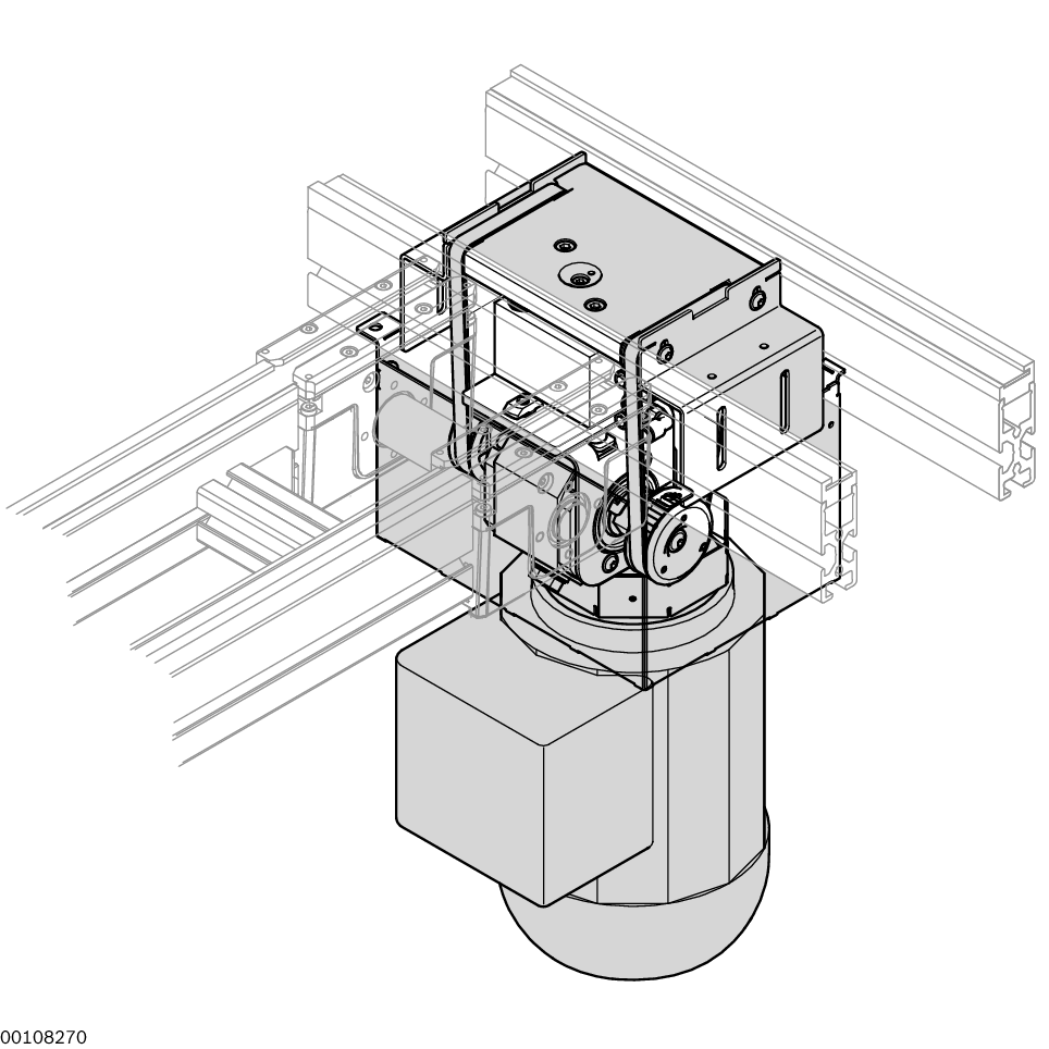
Lift transverse unit HQ 1/U

| 1) | Lift |
| 2) | Protective housings |
| 3) | Transport direction of longitudinal conveyor section |
| 4) | Transport direction of transverse conveyor section |
Transverse conveyor of workpiece pallets WT 1 when passing from a longitudinal section to a transverse section or when transferring from a transverse section to a longitudinal section.
It is also suitable for use in ESD applications.
Reversible operation is permitted; accumulation operation is not permitted.
Energy efficiency – Rexroth 4EE

Circuit diagram for unit with pneumatic equipment for two positions PN = 2

| 1) | Not included in the scope of delivery |

Circuit diagram for unit with pneumatic equipment for three positions PN = 3

| 1) | Not included in the scope of delivery |
|
No. |
3842998010 | ||
|
Max. total weight of workpiece pallet |
mG |
kg |
3 |
|
ESD |
yes | ||
|
Cleanroom class |
ISO class 7 | ||
|
Dry room |
r.F. |
% |
<1 |
|
Reversible operation |
permitted | ||
|
Required compressed air connection |
p |
bar |
4 ... 6 bar |
|
Pneumatic push-in fitting |
Ø |
mm |
4 |
Request Quote
How to Find Us
If you have any questions, just fill in the contact form, and we will answer you shortly. If you are living nearby, come visit us.